Tuesday, February 11. 2014
Z80 Proto Coming Along Nicely
I've rebuilt my previous Z80 computer and have been adding several peripherals of late. I think that ultimatly, after I decide the final design, I'll rebuild the whole thing to look pretty and be better laid out for higher clock speeds, but for now I'm continuing to prototype here.

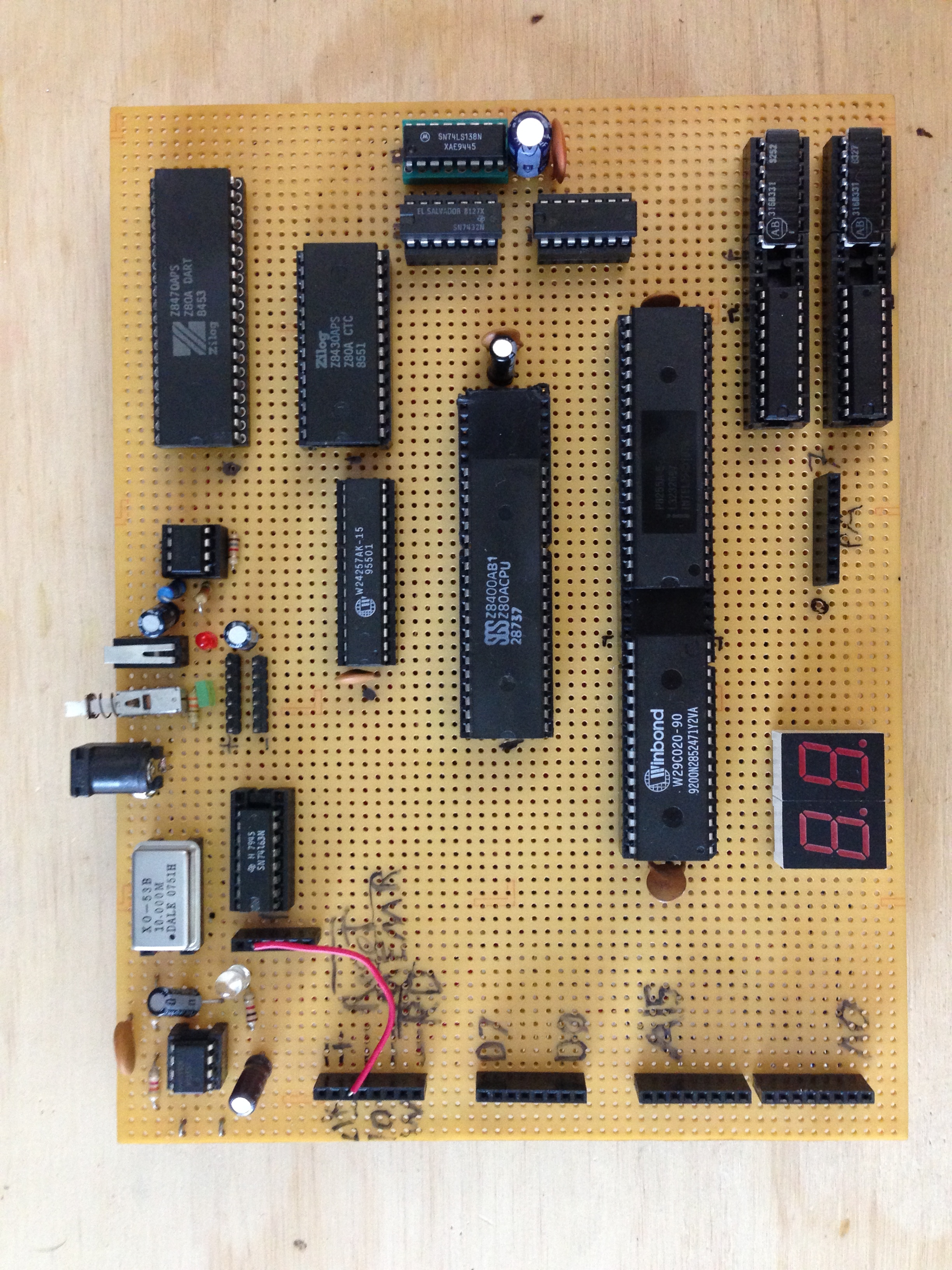
As it stands, I have the following systems configured:
CPU: Z80A - While I have some later devices with more features and faster clocks on hand, I'm testing base functionality with a run-of-the-mill original.
Flash: W29C020 - Boot ROM. The device is 256 kB, but I'm only using 32k (memory map is split between RAM and ROM). Technically I could enable write functionality to the flash, but haven't done so thus far as I haven't needed it.
SRAM: W24257AK - 32k. Haven't implemented any MMU or paging, but it would be trivial to do so in the future if need be.
Address Decoding and Glue: 74LS138, 74LS32, 74LS04 - Some people use PLAs or GALs to do this in a single device, but I have an attachment 7400 series logic.
General Purpose IO: 8255A - Provides three 8-bit ports per chip. Right now ports A and B are tied to 7-segment displays via 74LS244 octal buffers. Rather than use 7447 7-segment decoders to save 4 bits, I connected the displays directly so that I can display the A-F characters correctly via a map in ROM. This has been quite helpful while writing the BIOS.
Timing: Z8430APS CTC - This guy provides four counter channels with a handy list of prescalers and vectored interrupt features. Right now the BIOS configures channel 0 to send an interrupt every 10ms for polling routines, and channel 1 to provide a compatible baud rate clock to the DART.
Async Serial: Z8470APS DART - Contains a whole slew of serial comm features. Currently the BIOS configures channel A for 9600 8N1 and transmits debugging information through it.
System Clock: 10MHz Osc + 74LS163 Counter - The 4-bit counter provides clocks at 5, 2.5, 1.25, and 0.625 MHz, selectable via pin header. The 555 in the upper-left corner provides a 10kHz clock signal for visual debugging also, but at this point the BIOS is far too long to sit around waiting for it to boot at that clock speed.
Reset Controller: Analog! - At power on, a 1uF capacitor is slowly filled through a 1Mohm resistor to Vcc. When its voltage exceeds that set be a voltage divider (1/2 Vcc here), a comparator (TLC3702) releases the RESET_ assertion. A switch between ground and the capacitor provides another way to trigger a reset.
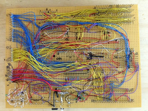
So far so good! Hopefully I don't jinx myself here, but I haven't made a single wiring mistake yet. I have the logic analyzer sitting here ready, but every time I've added a new chip the unit has just booted right up and worked flawlessly - I can't believe it, given the sheer number of connections.
By the way, I forked the assembler and fixed a few tiny things. Check it out on GitHub: z80asm. Also, I've spent a good bit of time writing emulations of the 8255, CTC, and DART in C as well as fixing the interrupt handling in my fork of z80sim: see my fork here. The file containing the my chip emulations is io.c (a work in progress at the time of writing).
Trackbacks
Trackback specific URI for this entry
No Trackbacks
Email me:
jack {@} crepinc.com
Recent Projects:
Analog HF Transmitter
Audi ECU Reverse Engineering
Dual DAC QAM Modulator
FPGA QAM Modulator
Geiger Counter
Gyro-Stabilized DSLR Platform
Hybrid Rocket Engines
Turbocharger Controller
WWVB Rx and Tx
Older Projects:
Balancing Bot
Capacitor Array
CNC Mill
DCIR Renderer
Electric Gokart
Hovercraft
Low Alt. Temp. Model
Shopping Cart Locker
Trebuchet
My Twitter occasionally shows projects I'm working on.
My GitHub has code from a few projects on it.